Ball Joint Replacement – 2006 F-350 SRW
“The balljoints are a press fit in the steering knuckle, which necessitates the use of a special press tool and receiver cup to remove and install them. Since the tool is not normally available to the home mechanic, it is recommended that the vehicle be taken to an automotive machine shop or other qualified repair facility to have the balljoints replaced.” - Chilton Ford Super Duty Pickups 99-06 Repair Manual
Yes, I bought that manual to help out with this job! Luckily, it didn’t come in before I started (and completed) the replacement of my balljoints on my 2006 F-350. I was able to find this very informative and helpful how to on the subject here:
http://www.superdutypsd.com/ball_joint_article.php
I printed this out and used it as a guide and referred to it often. My appreciation goes out to the author.
I decided to write a follow up or an addendum to the above referenced article due to the fact that my truck was a little newer and I had some unique circumstances and trials that made this job incredibly long (waiting on parts) and difficult (not having the correct tools). Had I known then what I know now, I would have been done much, much faster and with a lot less effort (and fewer trips to auto stores!)
OK, before undertaking this make sure you have the correct parts. I bought my ball joints from O’Reilly’s ($274.91). I went with Moog’s which are more expensive but supposed to be the best. If you drive a 2006 F-350 SRW like I do, all of your seals, o-rings etc. should be purchased at your Ford dealership. I know you might be tempted to buy them from your favorite parts guy at O’Reilly’s, but don’t. I did only to discover that they weren’t the right parts and I had to take them back to exchange them for the right parts. Unfortunately, only Ford has them ($163.74). Do rent your Balljoint press ($127.72 refundable upon return) from O’Reilly’s though.
Also, I would recommend having someone help you with this job, preferably someone with a vehicle (for running to parts stores, you will probably overlook something) and who has a pretty good set of tools. Also, someone pretty stout, we found it easier to just pound the old ball joints out than to use the press. But you will definitely need two people to do this.

Here are the part numbers for the seals:
BRS-170 (AC3Z-1S175-A), Need two of these, 1 per side

5C3Z-3254-AA, Need two of these, 1 per side

5C3Z-4A322-AA, Need two of these, 1 per side

You will need some specialized tools:
*The first and foremost of which is a big honking set of snap ring pliers. They have to be big, and long and skinny enough to get inside your hub and able to expand a snap ring that is an 1/8” thick.
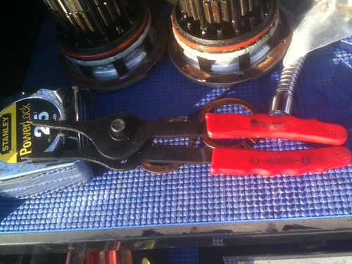

*Big torque wrench
Little torque wrench

Special tool for seating knuckle seal, purchased at Lowe’s for about $15 (2” pipe about 8” long with cap and floor flange. The really cool guys at the Ford parts counter were going to loan us the genuine Ford “Special Tool” but we took a socket the same diameter as my axle spindle up there and it was too small to fit on my axles. So this is a required but easily acquired purchase.
See below:

Special Tool for old balljoint removal. 1” pipe, 18” long with endcap. To the left you will see the other special tool that we fabricated for the stuck locking nut on the lower balljoint.

3 lb. sledge hammer (the yellow arrow is pointing to a snap ring off of the bottom balljoint. Not sure why...)

1.) To begin, jack the front end of the truck up and secure safely with jack stands. Please be careful with this and remember, repairing a truck is not worth dying for. Do not get in a hurry.

2.) Remove the front wheels.
3.) Remove the rubber ESOF vacuum line from the knuckle. Pliers can help.
4.) Unclip the ABS sensor wire from the quick release on the frame. The ABS sensor does not need to be removed from the bearing. Use an 8mm socket and remove the clip from the knuckle securing the ABS wire.
5.) Remove the caliper from the rotor using a 21 mm socket. The top bolt on the drivers side had to have a wrench.

6.) Use a tie down strap or rope to secure the brake caliper to spring. The arrow points to the top ball joint castellated nut.

7.) Remove the brake rotor. Tapping with a hammer may help to get it started, be sure not to damage the rotor surface.
8.) Remove the cotter pin from the castellated nut on the tie rod end, use a 21 mm socket to remove.
9.) We used a pry bar to gently work the tie rod off of the end.
10.) For ease of operation, we just removed the tie rod off of the other side and set it out of the way.

11.) Using a torx bit, remove the outer hub cover/bearing assembly from the hub. Be careful not to misalign the bearings.

12.) Using the big pair of snap ring pliers, remove the snap ring from the axle spindle.

13.) Remove the hub from the knuckle. There are four bolts that secure the hub to the knuckle and are accessed from the back of the knuckle. You may have to give it some love taps with a hammer to get it started. I believe I used a flat head screw driver to pry in between the hub and knuckle.
14.) Use a pry bar on the U-joint of the axle to get it started. We had to pound the back of the knuckle seal with a big punch to get it to move. Try to keep it going evenly all the way around. Once your past the lip in the knuckle it gets a lot easier. The axle should just pull right on out then. One side of my truck was a little tough so we tied a come along to it and just pulled it straight out. Luckily they both went in much easier. Both axles will have a plastic washer on them. When cleaning and re-lubing your axle, don’t forget to put these back on before re-assembly. They are what supports the interior spindle when lining up the axle to slide into the differential. The yellow arrows in the pic below are the plastic washers on the axle.

Here is what the knuckle seal looks like out of the knuckle...
Front:

Rear:


It should look something like this by now...

15.) Remove the cotter pin from the upper castellated nut and loosen this nut with the 1 1/8” socket. Leave it on a few threads to help catch the knuckle and keep it from falling on the pavement.

16.) Using the 1 5/16” socket, remove the locking nut from the bottom balljoint.
17.) Using your hammer, beat on the knuckle to it pops loose.
18.) Remove the top nut the rest of the way and set the knuckle aside.
Now the fun part begins. By now you may have some pent up aggression. Maybe you overlooked a critical socket or other tool and had to make a few runs to the parts store (we made 12 trips total over the course of the three days we worked on this project. Of course, had we had the correct seals to begin with we wouldn’t have had to wait till Monday for the Ford dealership to open!)
We used a 1X6 board about 6 – 8’ long, and using C-clamps, we secured the knuckle to this board. Then, using more C-clamps, we secured the board to a work bench at about waist level. (We discovered this on the second knuckle. Wish we would’ve known about this technique for the first one, which was much more difficult.) After removing the snap ring off of the bottom balljoint, pound the crap out of it with a hammer until the balljoint is flush with the knuckle. Then, using your special tool from Lowe’s (the 1” pipe with endcap) beat that balljoint the rest of the way out. Then do the same thing for the upper.
Using the press, insert the new ball joints into the knuckle. Do not lube them yet with the grease fittings. Put the snap ring on the lower one.
Reassembly
1.) Install the knuckle onto the axle. Use the top castellated nut to hold it in place while you start the bottom. Remember, the bottom nut is a locking nut. When you have momentum going with the socket, do not stop tightening. Otherwise the lock nut could lock down and then the ball joint will spin freely as you try to tighten or remove the locking nut. We had this happen and had to create another “special tool” from scratch that we could use to insert into the top of the balljoint shaft while using a wrench to get the nut off.
2.) Following the manufacturer’s torque sequence, torque both nuts to spec. If you’re using Moog’s, the top nut is probably a 1 5/16” socket just like the bottom one now. You may have to use a jack to apply pressure to the bottom of the bottom ball joint. We did.
3.) Install the cotter pin into the top ball joint. If the holes are not lining up, tighten slightly till they do. Never loosen.
4.) Once the knuckle is installed back on the axle, install the grease fittings into the ball joints and lube according to the manufacturer’s instructions. You may have to remove these if they don’t clear your U-joints. I didn’t have to.

5.) OK, the axle dust seal has been redesigned. So the one that was dangling loosely on my axle is not what I received. Apparently Ford has redesigned these and hopefully the new ones will work much better. So, take the plastic washer off of the axle.
6.) Take the old rubber dust seal off the axle.
7.) Slide the new dust seal onto the axle. It will kind of slide up into the axle housing and fit flush when you’re done.
8.) Slide the plastic washer back onto the axle just past the spindles.
9.) Slide the axle back in, it should slip right into the differential with minimal effort.
10.) Support the end spindle (at the U-joint) and slide the new knuckle seal into the knuckle. Don’t worry it won’t go in very far. Yet.
11.) Using special tool 2, the 2” pipe with end cap and flange, slide the flange over the spindle until it is flush with the seal. Now you want to evenly slide this seal back to where it is flush with the knuckle. It is a good idea to look at the back side of the knuckle before you take the seal out to see where it needs to slide back to. My seals did not seat on the axle and then just slide in to the knuckle. We popped the seals out first on removal and then slide the axles out.
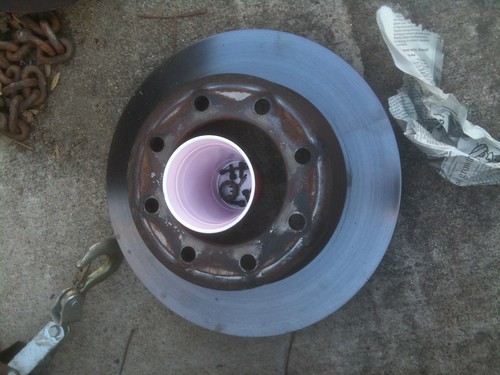
12.) Now it is time to reinstall the wheel bearing/hub assembly. Use a pick and remove the old yellow O-ring and install your new one. My new one was black instead of yellow now. The yellow arrow shows the new O-ring installed.

13.) Slide the hub onto the knuckle and start the bolts tightening in an even pattern, alternating diagonally to seat the hub evenly onto the knuckle.
14.) Reinstall the snap ring into the hub. It went in much easier than it came out.
15.) Put your rotor back on. Use a lug nut to hold it in place. (I didn’t do that, but it would’ve been easier when trying to get the caliper back on!)
16.) Reinstall you caliper.
17.) Reinstall your ABS sensor and vacuum hose.
18.) Reinstall your tie rod.
19.) Put your wheel back on and make sure it spins smoothly.
Anytime you’re doing an operation of this magnitude, it is always a good opportunity to check other systems and do work on them as necessary. I needed to replace my brake pads. It is just much easier if you can do some other work in this area of the truck while you have everything broke apart.
I’d like to extend the warmest and sincerest thanks to my brother-in-law, Joe Don for his help and tools. I definitely could not have done this job with out him. And super extra special thanks to my sister who is always doing sweet things like bringing hot chocolate out at 10 o’clock at night when it is bitter cold to two morons who don’t have any better sense than to be pounding ball joints out of a truck!
Good luck to you in your mechanical quest to make your truck run/perform better. I’d highly recommend taking your truck to the Ford dealership and letting the parts guys run your VIN and get you exactly the right parts/seals you need. Price-wise, O’Reilly’s will not be cheaper at all if you're given the wrong stuff.